I've been removing the three axle valves from the W112 300SE coupe to send them away for rebuilding. The rear stays up, but I'm sending it anyway. So I took the oportunity to use my little Kodak camera to take some shots as I went along in the hope it will be useful to someone. The car is back home here, so it is on stands, not the comfort of the hoist at Justin's. We also have a jack under the front subframe to give it and the motor a bit of support while the stands hold the body.
The left front valve is the worst to get off and worse still to get back on. The W112 is easier by far for this valve than the 6.3 which has steel pipes to all 7 connections. The time to do the 6.3 valves is when the front subframe is out of the car for any reason. It is a dog of a job on the car.
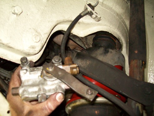
Further down is a picture of the left front valve after I removed it. It has two high level connections to the brass part. It has an end inflow connection on the left and a lower inflow connection on the bottom side at the left. In the middle on the bottom is the connection for the left front air bellows. On the right are the two outflow connections, one at the end and one at the bottom. In contrast to the 6.3, in the 300, three of the connections have hoses attached rather than steel pipes making life easier. The two end fittings and one of the high level fittings have the hoses.
I undid the end E fitting first. You can see the threaded fitting in the middle of the picture at the top. The hose allows the end to move a long way out of the way. I then undid the three bottom fittings, doing the E nearest the camera first, then the B in the middle and then the A last. At the time I took the picture, I had just started on the far A fitting with my 14mm open end spanner on the brass attachment on the valve and the pipe spanner (flare nut wrench) on the pipe fitting. Squeezing the two spanners together cracks the thread. Then you have to use an open ended 12mm spanner to undo the rest.
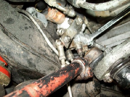
This is RHD but you can see how the steering mechanism is in the road. I've undone the two high level lines as well. You can't use the two spanner technique on them, because there is nowhere for the 14mm spanner to go. There is not much room up there. You can see it better in the pictures I took on the other side. You can see that I still have the ball joint for the control rod intact. That was not deliberate, it just happened that the lower ball on the lower control arm let go before the one on the valve arm.
This picture is a bit fuzzy but it shows the bottom E,B and A pipes undone across the bottom of the valve unit.
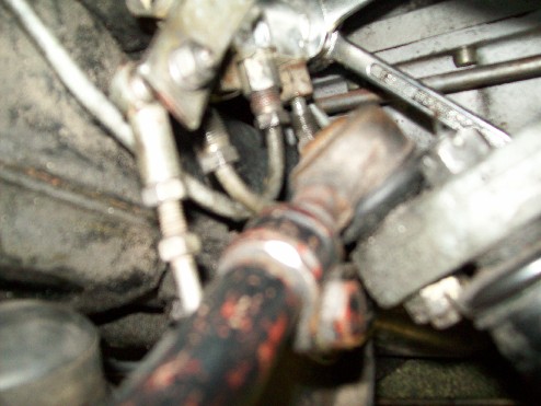
This is similar from a bit further back.
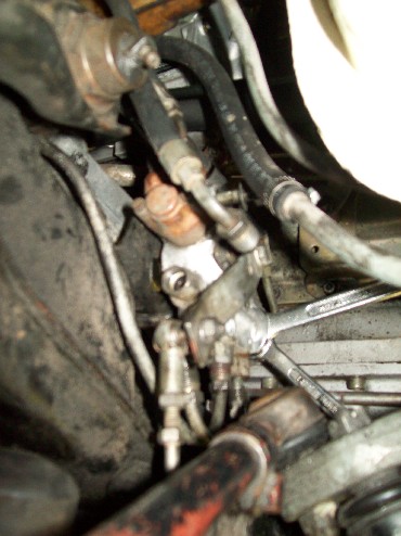
I shoved the camera up behind the steering damper to take this. I didn't see it from this perspective myself. Note the in the past, someone has had trouble with the nut on the A fitting rounding off and has filed it down to a square 10mm.
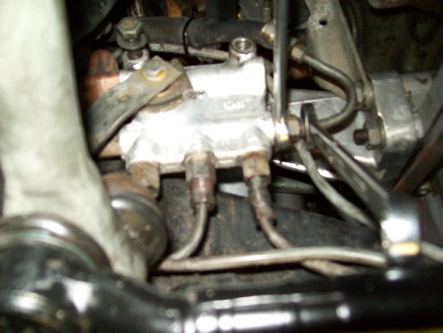
You can also see that I have the valve retaining bolts loose and in fact, the right one is out. A 13mm long socket spanner did the job for them on this side as there was plenty of room.
And, after all that and the nice pictures of the two spanners, the pipe spanner just rotated on the far A fitting, so I gave up last night when I did that job and started again this morning with the vice grips to release that fitting, again with the 14mm open ender on the valve end. So that will be another thing to fix before the unit goes back in. Here is a picture showing where it came from. At the top you can see the two high level lines above and in front of the end E hose fitting. The three lower pipes are obvious with the B line sticking up more than the other two. At the far end you can see the A hose end fitting. In the middle is the bracket with the two welded nuts at the top.
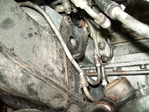
This gives a good view of the two high level pipes (the inflow one from the master valve is a hose). That's the B line tracking up to pass inside the trunion where it should be protected by two thick rubber hose spacers.
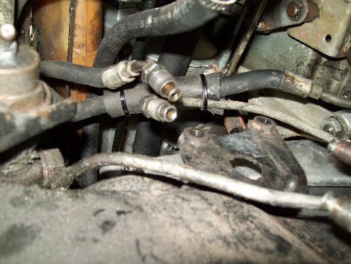
The set up is the same on the 6.3, you just don't have the luxury of the rubber hoses. Here is another general view.
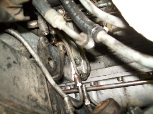
And it is out[:)]
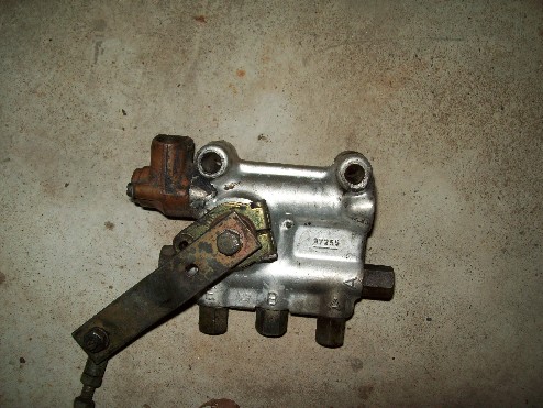
Now the right side. This should be pretty straight forward on LHD cars. On this car, the steering box and arm are in the way. There are three less lines, one high level and the bottom A and E lines. You can again see the B line tracking up behind the subframe to go across the top to the bellows, missing its rubber protective hose. I've bought a metre of the hose to fix this up as well as to use on Justin's and other projects.
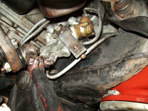
Here is a close up. I've got the control rod off the correct end this side. That's the front of the power steering box and steering arm protruding in from behind. No room for a socket here. You can see that I have got the B line started. If it won't undo with fingers, it is tedious, because there is only enough room for a part turn of the 12mm spanner which has to be repeatedly reversed. This applies a lot doing this. The E line just above the control arm is straight forward on this side.
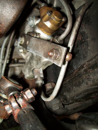
I've cracked the high level line with the pipe spanner and have managed to get my hand up in there to undo this line with my fingers.
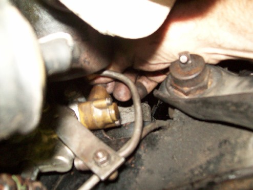
Now I'm working on the A fitting at the far end. That funny looking yellow thing is the palm of my hand squeezed in above the steering arm in front of the power steering box with my trusty 12mm spanner. I've already done the two spanner trick to crack it. You will notice that the rubber spacer is missing from the bracket holding the three lines to the back of the subframe in the distance. That is another job for me. If it were there, I would loosen it anyway while working on this line, particularly when reinstalling this valve.
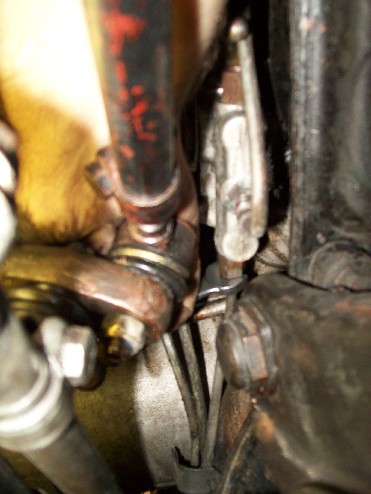
I've decided to release the unit before I finish undoing the A line because I can't get it free enough to use my fingers, and there is no room to swing the spanner. So now I am undoing the two bolts, outer one first. With the power steering in the road, I cannot fit a socket and am using a closed 13mm spanner. You can see the end of the released high level line above the end of my thumb.
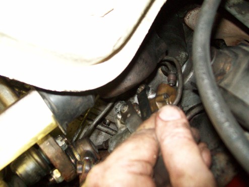
Here is another view of the same thing.
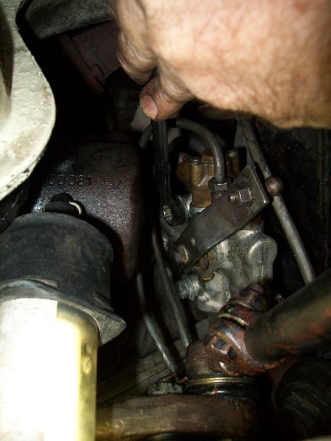
Now I'm onto the inner bolt. I remembered when I changed this valve recently that the bolts had to go into the unit before the unit went into place, because with the unit in place, there was insuffient room to get the bolt into its hole because the power steering box was in the way. I don't know if that is the case on the left in LHD cars, but it is worth bearing in mind.
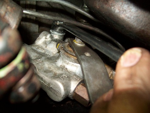
Now with the unit free, I can get my hand in to undo that A fitting with my fingers. That's the brake line ruining the picture. There really is not much room[:(].
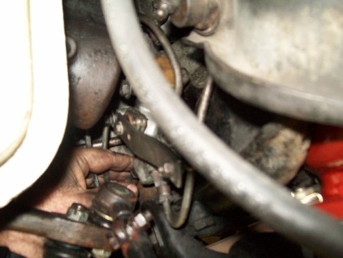
And it's out[:)].
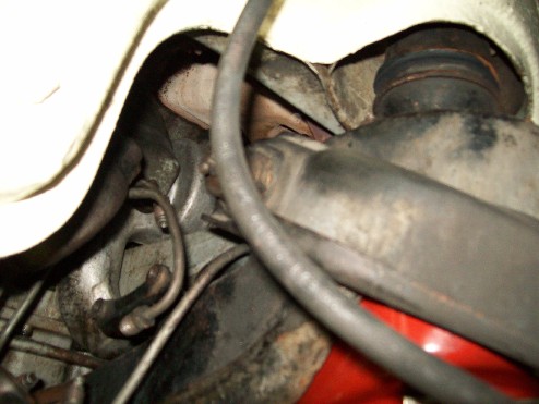
Couple of shots of where it came from.
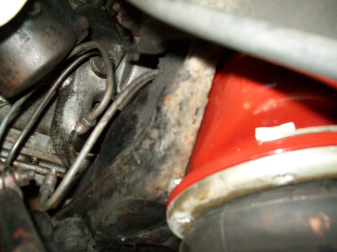
Now the rear one.
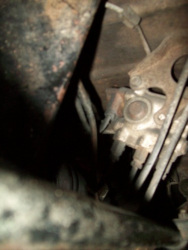
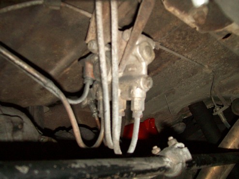
This is very accessable with the exception of a problem I recall having before. That is getting the high level fitting undone. The two spanner trick works easilly here on the A,B and E lines. As at the front, there is nothing on the valve unit for the 14mm spanner and I found there was only one way I could apply the pipe spanner (flare nut wrench I think you call it) and that was in the most mechanically disadvantagous position for my hand. You have to undo the fittings before you undo the two bolts, and at the rear, the nuts are not welded, so you need a 13mm socket and a 13mm spanner.
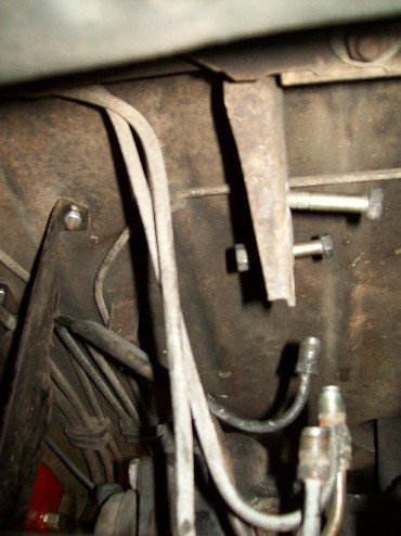
When the units come back, I'll complete this thread with some words and pictures on reinstallation. Hope it is all helpful for someone.
Art