help_outline Skip to main content

6.3

K4B 050 Transmission
aplekker

Since the transmission was out of my car, and it shifted rather harsh, I decided to take a good look at it.

First observation was leakage, mainly from the rear cover and the speedo meter cable mount. Also, I found out that the lever that is turned by the 2 way solenoid was frozen solid in the modulating pressure control housing.

I removed the housing, and also removed the brake band pistons B1 & B2 to check their sealing rings. This was a mistake, since I heard something falling down inside the transmission, which later turned out to be the pin between the piston and the brake band.
Then I decided to take the whole transmission apart, and completely reseal it.

Some interesting facts: this transmission must have been rebuilt sometime in the past, since 3 parts were missing: two wire locks that keep lock rings in place, and the lock ring for the output shaft connection to clutch K2.

Also, the bearing on the output shaft in the rear transmission housing turned out to be cracked.
My clutch spring compressor, which is designed for the 722.3 transmissions, is too small for the K1 and K2 clutch packs. I will have some rings made in order to use this compressor on these clutches.

Below some pictures. If there is any interest, I will put some photos up when this thing goes back together.

Here the complete gear train:


A close up of the gear train, see the burn marks from brake bands B1 & B2. B3 (left) has none, since it engages the reverse gears...


The cracked bearing on the output shaft...


Another look at the cracked bearing. See also the plate the connects into clutch K2, which was missing the lock ring...


Ron B
Talking with someione recently,they said tyhat often you find those rings in the oil pan....That must have been a growly transmission with that busted bearing. When I see the scorch marks on the drums I could understand how someone has broken the bearing race. How are the linings?

quote:
12-14-2004, 11:49 PM #8
Tom Hanson
MBCA Member

What the heck, try to stuff a MB 6.9 liter V8 in it. What a machine that would be..
__________________
Tom Hanson
Orange County Section
aplekker
Ron,

The linings seem OK to me, I will post some pics later tonight and maybe you can give your opinion.
The clutch plates also seem OK.
However, I workshop manual and the EPC show 4 lined clutch plates (with Innenlamellen) for the K2 clutch, and I have found 5...
Any ideas? This is a late style transmission.


Chris Johnson
This is a subject I am very interested in right now. The engine for the 600 is at the machine shop right now, and the transmission is still sitting in the garage. While still in the car, the transmission looked like it was leaking from every possible location that it could possibly leak. I would like very much to pull it apart and reseal it before putting it back in the car.

The problem is that the internals of the automatic transmission is where I have always drawn the line in the past. I'll pull a valve body apart, but that's it.

One of my concerns has been the spring compressors. What is involved in making the 722.3 tool work? Would you post some photos?

Is it realistic to think I can get into this myself, and do it succesfully?

Chris Johnson
If you aren't constantly impressed with your car, then it needs fixing.
100.012-12-000790
100.012-12-000867
www.300SE.org
bwostosh
If it had been apart before, did someone add the extra plate to compensate for some worn parts rather than get new clutch parts,
What are the dimensions of new / old clutch parts?
Do you mic them?

Brian O.
aplekker
Chris,

I think redoing a transmission is definitely something you could do. As a matter of fact, the K4B 050 transmission is, IMHO, a lot easier to do than a 722.3, since you can get to both sides of the transmission housing. The only special tool needed is the compressor for the clutch springs. I had some rings made to use the 722.3 tool, and after trying it tonight I found out that I need a refinement for the K1 clutch, but it worked great for the K2 clutch.

The manual talks about a tool for removing the piston housing for the B1 & B2 brake bands, but I found out that this tool is not needed. I used some longer bolts and the housing came off easy. Also, the guiding tool for getting the clutch pistons back in is not needed, I used a very cheap guiding tool that is nothing more than a very thing wire in a holder, and it slips the lip of the seal right back in.

Setting the clearances does not seem to be a big problem, specially if you only reseal the tranny and not change any of the bearings, clutches or brake bands. If it was me though, I would replace everything that wears while you are at it.

I have done three 722.3 transmissions with 100% success.

Below a photo show on the compressor story.


The original 722.3 compressor:


The compressor mounted on a 722.3 clutch:


Compressor mounted on 722.3 pack before compression:


and after compression (notice locking ring):


K4B 050 K2 clutch:


K2 clutch:


The 2 adapter rings, bottom left and middle:


Detail of the main adapter ring (needs changed!):


Compressor with adapter rings on K4B 050 K2 clutch:


Detail of other ring, needed because the original tool nut is too small for the K4B 050 clutches:


Detail of main ring:


Before compression:


After compression:


With locking ring removed (this locking ring mounts on the bottom instead of top):


Spring retainer removed:


Springs:


Piston removed:


Problem with adapter ring on K4B 050 K1 clutch: there should be a relief in the ID of the adapter ring, so the spring retainer can go through the ring, so you can remove the locking ring. Stupid, but those things happen. I will see if we can get that done tomorrow.


aplekker
Ron,

Here some pics of the bands. I don't think they look too bad. Please let me know what you think.

B2 band:


Detail of B2 band:


Detail of B1 band:


Ron B
Hi,those bands don't look like they have many miles on them. Perhaps they were changed at some time. Closely examine the ends where the pin pushes against them ,that's the bit that breaks off.
That may also explain why there is an extra plate in the clutch. There are 9 different thickness available,you should have the installed height specs in your manual (section 27-0) . There are three different lengths for the band pins too.

The compressor you are using in similar to the factory tool,but the factory is pressed with a press ,which not everyone has.

Chris,if you have the Finny workshop manuals from 1959 onwards,the DB auto trans part covers most of the transmission work ,the 6.3 part is really only a supplement to this.

quote:
12-14-2004, 11:49 PM #8
Tom Hanson
MBCA Member

What the heck, try to stuff a MB 6.9 liter V8 in it. What a machine that would be..
__________________
Tom Hanson
Orange County Section
aplekker
Yes, the workshop manuals from 1959 on are very good, the main difference I see is the assembly/disassembly of the gear train, which is obviously different. The 6.3 supplement covers that, although I found a German version of the 1959 on etc manual that covers the K4B 050 even better.
I am still a little confused with the parts manuals, they show the clutch K3 and not the one-way clutch that is mounted in this transmission.

I will measure both clutch packs today, and publish the results later.
Chris Johnson
Thanks guys,

I have all the regular service manuals, as well as the transmission supplement from 1963 which is about 150 pages. At one time I had the K4B050 supplement when they were still available from MBNA, but that has grown legs sometime over the last 20 years. I know there have been recent posts about where to locate this particular supplement, so I'll have to go chase down one of those.

I agree that once the trans is apart, it is time to renew anything that is questionable. I'm going to give this a lot of consideration before doing anything, but if I decide to jump, I hope you all will be available for advice.

I'm amazed at the broken bearing. I've never seen anything like that before. I can only wonder what in the world would cause something that severe. My first concern would be that the bore that it fits into isn't round anymore.

There is a note in one of these manuals about a change in the number of clutch plates, but it is my memory that this change took place immediately before the 6.3 went into production implying that only the 600 would have actually seen the change in production. All 6.3s would have already had the greater number of plates. I'll see if I can dig this up since it may be relevant to what you are seeing. Which version of the parts book do you have?

Chris Johnson
If you aren't constantly impressed with your car, then it needs fixing.
100.012-12-000790
100.012-12-000867
www.300SE.org
Chris Johnson
quote:
I have all the regular service manuals, as well as the transmission supplement from 1963 which is about 150 pages. At one time I had the K4B050 supplement when they were still available from MBNA, but that has grown legs sometime over the last 20 years. I know there have been recent posts about where to locate this particular supplement, so I'll have to go chase down one of those.


Uhh, okay, I have the K4B050 supplement too. It turned up in a box this past summer. I guess I just got used to the idea that it was gone. I'm going to use my advancing age as an excuse.


Chris Johnson
If you aren't constantly impressed with your car, then it needs fixing.
100.012-12-000790
100.012-12-000867
www.300SE.org
aplekker

After the transmission case is cleaned (soda blasted) I will check the bearing bore for any damage. We will have to make a ring and machine the case if there is damage.

I think you are right about the K4B 050 clutch plate change: that took place at transmission # 1391, and from the start of production of the 6.3, as stated in the Grand 600 manual. So I assume my 600 has the old setup, and the 6.3 has the new one. I have a spare K4B 050 transmission in storage, have to find out what serial number, it might be usable for either the 6.3 or the 600.

I use an off-line EPC from 2001 (the Bell & Howell version) for most of my parts searches, since it is fast. For more up-to-date checking I subscribed to the on-line EPC, which is slow, but sometimes different from the 2001 version. It also shows the parts for my 2003 CL600.
The paper version for the transmission is Edition F, 10146 from 1968. However, that does not cover the K4B 050, but all the drawings are the same as in the electronic versions.

1965 600 SWB #248
1968 6.3 #0347
1971 6.3 #5745 Euro
1979 6.9 #6857 Euro
1979 450SLC 5.0 EURO
1981 300SD
1989 560SEL
2003 CL600 Brabus 570HP
Chris Johnson
Albert, you've got a number of these transmissions and I've got an extra copy of the K4B-050 transmission parts book (10 153 Ed. A). It seems to me you should have it. I'll contact you off-line.

Chris Johnson
If you aren't constantly impressed with your car, then it needs fixing.
100.012-12-000790
100.012-12-000867
www.300SE.org
Ron B
I thought about the extra clutch as mentioned in the 600 section too but as you say it really only relates to cars built before the 6.3 production. . I think from memory that the case is slightly longer on the later ones?
My only spare trans is the one I broke the band in and I haven't had time to pull it down yet.

quote:
12-14-2004, 11:49 PM #8
Tom Hanson
MBCA Member

What the heck, try to stuff a MB 6.9 liter V8 in it. What a machine that would be..
__________________
Tom Hanson
Orange County Section
aplekker
The clutch situation is getting really bizarre. The way I found the clutches in my transmission is completely off from the way it should be according to my manual.
The manual I am using is a German supplement for PKW Typen ab 1968, Baureihe 108-115, from January 1972. The header: Automatische Getriebe K4B 050, Typ 300 SEL/8 6.3

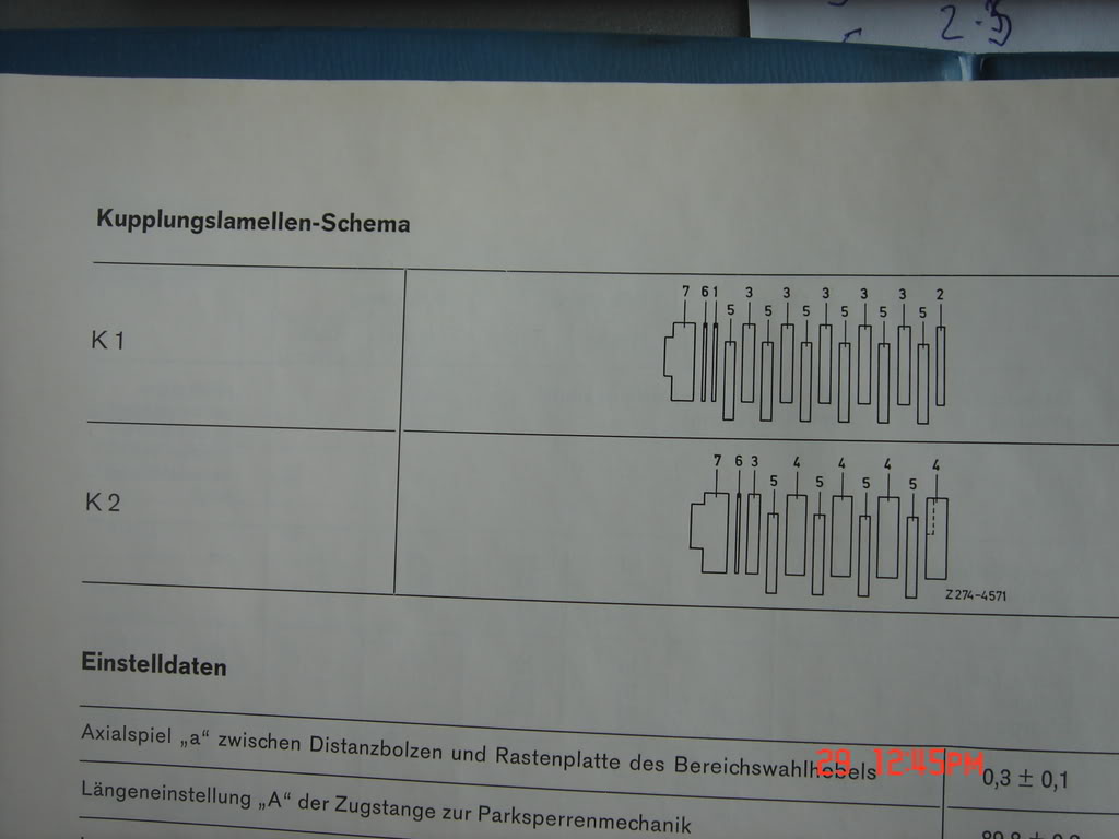
On page 27-10/4 it shows the clutch layout for both clutches:

K1: 6 1 5 3 5 3 5 3 5 3 5 3 5 2

K2: 6 3 5 4 5 4 5 4 5 4

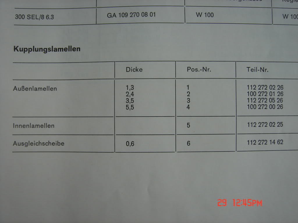
1 Steel 112 272 02 26 1.3mm
2 Steel 100 272 01 26 2.4mm
3 Steel 112 272 06 26 3.5mm
4 Steel 100 272 00 26 5.5mm
6 Steel 112 272 14 62 0.6mm

5 clutch plate lined 112 272 02 25 2.5mm

That means K1 has 14 elements with a total thickness of 36.8mm, and K2 has 10 elements with a total thickness of 36.1mm.

What I found:

K1:
3.0 Steel P
2.2 Lined
5.5 Steel P
2.3 Lined
5.0 Steel P
2.4 Lined
5.0 Steel F
2.3 Lined
4.5 Steel P
2.4 Lined
3.5 Steel F

K2:
4.5 Steel P
2.5 Lined
3.5 Steel F
2.5 Lined
3.5 Steel F
2.5 Lined
3.5 Steel F
2.5 Lined
3.5 Steel F
2.5 Lined
6.3 Steel F

Steel F is a steel plate with full teeth on the outside diameter, Steel P has 4 times 3 teeth on the outside diameter, Lined are the clutch plates lined with the friction material.
What we can see in K1 is that most lined clutch plates are worn down from their 2.5mm initial thickness, while in K2 these lined clutch plates are all still 2.5mm.

Also, both K1 and K2 have 11 elements. If you take the full 2.5mm for all clutch plates, K1 ends up being 39mm and K2 37.3mm. That is 2.2mm difference from the spec for K1 and 1.2 mm for K2. That is definitely outside of the tolerance, which is 0.6mm for K1 and 0.4 mm for K2.

What we also see is the in both clutches:
- The first 0.6mm steel plate is missing.
- K1 should have 6 lined plates, I have 5.
- K2 should have 4 lined clutch plates, I have 5
- K1 should have 3.5mm steel plates between the lined plates, I have a variety.
- K2 should have 5.5mm steel plates between the lined plates, I have the 3.5 mm ones.

I thought I might have confused K1 and K2, but that is definitely not the case, I have many pictures on how this came apart, and it is very obvious where each pack came from. The housing and pistons for K1 and K2 are completely different.

The only conclusion I can draw is that the previous rebuilder messed things up pretty bad. The fact that the K1 plates are way more worn down than the K2 ones also might be an indication that things were wrong, since K1 should have had 6 plates.

Any one have any ideas???


1965 600 SWB #248
1968 6.3 #0347
1971 6.3 #5745 Euro
1979 6.9 #6857 Euro
1979 450SLC 5.0 EURO
1981 300SD
1989 560SEL
2003 CL600 Brabus 570HP
Ron B
Missed one plate so they put in the next clutch pack they were assembling?[:D]

I had a look in the tool catalogue and the only special tools needed for assembling a trans ,apart from the clutch assembly tool ) are clamps to press the side covers back on to the pistons. And anyone can make one ,it's very simple.

quote:
12-14-2004, 11:49 PM #8
Tom Hanson
MBCA Member

What the heck, try to stuff a MB 6.9 liter V8 in it. What a machine that would be..
__________________
Tom Hanson
Orange County Section
aplekker
True about the special tools, other than the socket for the nut in the three legged flange on the output shaft.

I also have the pressure gages you hook up to the tranny and hang in the car while you drive it. Very handy.


1965 600 SWB #248
1968 6.3 #0347
1971 6.3 #5745 Euro
1979 6.9 #6857 Euro
1979 450SLC 5.0 EURO
1981 300SD
1989 560SEL
2003 CL600 Brabus 570HP
aplekker

After a lot of digging around, mainly in the online EPC, I found out what MB has available and lists as the proper setup of the K1 and K2 clutches. Since I subscribe to this EPC, I can access the info to all the MB products around the world, and by searching for part numbers you can get more info, like the thickness of the clutch plates.

Here we go: (referring to the pics on the first page of this thread)

K1: 6 1 5 3 5 3 5 3 5 3 5 3 5 2

K2: 6 3 5 4 5 4 5 4 5 7

where 6 is closest to the piston and the numbers refer to:

1: 109 272 15 26 2.0mm Outer Steel $9.00
2: 100 272 08 26 2.4mm Outer Steel $24.00
3: 109 272 08 26 3.5mm Outer Steel $16.50
4: 109 272 05 26 5.5mm Outer Steel $54.00
5: 112 272 02 25 Inner lined $13.88
6: 112 272 14 62 0.6mm Steel guard plate $7.31
7: 109 272 18 26 5.0mm Outer Steel $37.50

These should all be available from MB, and I ordered some more of the #6's in order to be able to adjust the clearance.

The brake bands are another story: we all know these are not available from MB, I have two companies that are saying these bands can be relined. We will see.

I also ordered the gasket kits, there are 4 per transmission. Also ordered the ball bearings, some clips and locks, etc.

Some special attention for the speedo meter cable attachment: this is an aluminum housing, and there is a 6mm bolt for clamping the speedo meter cable. This part is often cracked, since people try to tighten it too much. Of course mine was cracked, causing a slow but very irritating leak. Part # 112 270 01 13, for only $428.00.....


1965 600 SWB #248
1968 6.3 #0347
1971 6.3 #5745 Euro
1979 6.9 #6857 Euro
1979 450SLC 5.0 EURO
1981 300SD
1989 560SEL
2003 CL600 Brabus 570HP
cth350
That 112 part number implies that there are several used cores out there. Is it fixable via some tig welding? -cth
Chris Johnson
Cores? I have at least ten spare 300SE automatic transmissions. I'll have to pull one off and verify it really is the same part.

Chris Johnson
If you aren't constantly impressed with your car, then it needs fixing.
100.012-12-000790
100.012-12-000867
www.300SE.org
aplekker
Yes, it is used on all 16 bolt pan transmissions, as far as I can see. But that is the MB list price, I was lucky and found one on EBay for a third of that (actually from Gary).

I am not an expert welder, but I think it would be impossible to weld. However, we have some good welders, I will ask them next week.

The main reason I mentioned this part is the leak problem. It is hard to see the crack.

1965 600 SWB #248
1968 6.3 #0347
1971 6.3 #5745 Euro
1979 6.9 #6857 Euro
1979 450SLC 5.0 EURO
1981 300SD
1989 560SEL
2003 CL600 Brabus 570HP
aplekker
I finally got to the clutch compressor issue. A new adapter ring was made, and it works. See the pictures below.

A word of caution: there are 24 springs in the K1 clutch, and these are a lot heavier that for instance the 722.3 clutch springs. They are also longer that the 722.3 springs. DO NOT use a cheap universal spring compressor, the force to compress the spring is tremendous and the distance to relieve the springs is larger.
Also, do not try to use a large vise or a drill press, you will take a large risk to get hurt.

The new adapter ring:


The K1 clutch as it comes out:


The K1 clutch with the tool mounted:


Setup before compression:


Setup after compression (notice the lock ring):


Lock ring removed:


Springs completely relieved (notice the LONG distance to go):


Tool removed:


Spring retainer plate removed. Notice how heavy these springs are:


1965 600 SWB #248
1968 6.3 #0347
1971 6.3 #5745 Euro
1979 6.9 #6857 Euro
1979 450SLC 5.0 EURO
1981 300SD
1989 560SEL
2003 CL600 Brabus 570HP

Ron B
Hi,I mentiojned before that the factory compressor is designed to be used in a hydrualic press...definitely a lot pressure! it has to withstand the m-100 torque[:D]

quote:
12-14-2004, 11:49 PM #8
Tom Hanson
MBCA Member

What the heck, try to stuff a MB 6.9 liter V8 in it. What a machine that would be..
__________________
Tom Hanson
Orange County Section
aplekker
Here a short picture story on the main pump, the governor and both small pumps on the output shaft.

Took these apart today, since the rest of the transmission is apart anyway, and I do not want to take the risk of more surprises like the cracked bearing.

No big surprises, although I found a large clump of crud of the pressure control piston in the rear bearing cover. That does not make me feel good about the valve body and the governor itself.
The governor can be taked apart, but the covers 1-4 are locked into place. I could take these covers off, but am not sure if that is a good idea. Any one have any ideas on this?


Front cover with primary pump:


Sealing rings, these hook together:


Pump gears:


Rear bearing housing with the govenor on the right and both pumps on the left:


Governer with four numbered fly weight chambers:


Governer stepper pressure transmitter piston on the top and pressure control piston on bottom:


Look at the crud:


Secondary oil pump:


Governor oil pump:


All parts of both pumps. The governer oil pump gears have a larger relief on one side, that faces the pump housing.


1965 600 SWB #248
1968 6.3 #0347
1971 6.3 #5745 Euro
1979 6.9 #6857 Euro
1979 450SLC 5.0 EURO
1981 300SD
1989 560SEL
2003 CL600 Brabus 570HP


aplekker
Today I took the valve body apart. The K4B 050 manual I have is an original German manual, chapter 27-18, and a copy of the corresponding English manual.
The valve body top and base came apart easily, and all parts are as in the manual.
However, what MB calls the "oil distribution plate", which is basically the part of the assembly you will see after removing the filter, has some differences.

Venting bushing 34b was completely stuck, after removing pin 34c. I finally got it to move, but cannot get it out of the bore. Right now it moves freely in the space that is allowed by the pin, so it should be OK. Any one with any ideas???

Then, venting valve K1 (27) is a completely different part from the picture, and spring 27a is missing.

Finally, venting valve K2 (28) is also different, and spring 28a and washer 28c are missing. Now both parts 27 and 28 are the same shape, and these are both clutch venting valves. Did MB make a change??? Anyone has any idea???

For any one interested how I did this job: I take the pistons and valves out according to the manual, lay them on a piece of paper in the exact way and orientation they came out, and then took close up pictures. Then I store all parts in a parts box, after writing down which is where. After cleaning everything I will put it back together.


The valve body base with range selecting valve on top:


The valve body base:


Valve body base one side:


Valve body base other side:


Valve body top one side:


Valve body top other side:


All stored:


Oil distribution plate one side: (see bottom different K1 venting valve)


Oil distribution plate other side: (see bottom different K2 venting valve)


manual pages:


manual pages:


manual pages:


1965 600 SWB #248
1968 6.3 #0347
1971 6.3 #5745 Euro
1979 6.9 #6857 Euro
1979 450SLC 5.0 EURO
1981 300SD
1989 560SEL
2003 CL600 Brabus 570HP
aplekker
Well, since no one replied I decided to take the valve body off of one of my spare transmissions in order to find out what is going on with the different valve setup.
And guess what: they are exactly the same, so I assume MB made a change and never updated the manuals.

However, I have an issue, and I will have to get my (small) soapbox out. It really blows my mind that I have posted some questions in this thread (specially the last one about the valve body, and the one about the clutch issue) and no one comes up with anything. There have to be people around that read this bulletin board and that know the answers. Is it some kind of secret? In my opinion this bulletin board is there to expand all of our knowledge, and should serve as a deposit for all of our combined knowledge.
The professionals under us should have no fear about us taking their business, most people will leave that kind of work to them.
It took me 5 years to gather all the manuals that I have, some in horrible photo copy format. I also acquired some literature that was produced for inside MB use. But it is in all our best interest to share this info, and to put it on this bulletin board in order to preserve and spread it.

Am I off track here???

1965 600 SWB #248
1968 6.3 #0347
1971 6.3 #5745 Euro
1979 6.9 #6857 Euro
1979 450SLC 5.0 EURO
1981 300SD
1989 560SEL
2003 CL600 Brabus 570HP
paul-NL
Albert,

I am sorry, but have no knowledge about transmissions ....
Can't help you.
Art Love
Jeeez Albert,

You are teaching me here. I've had at least 10 people try to explain to me how an automatic transmission works and I still haven't a clue. Those valve bodies always remind me of an old English maze. As soon as anybody starts to explain the mechanism, my mind goes into neutral[xx(], not the gearbox[:I].
[:D][:D][:D],
Art
Ron B
Hi Albert,I looked at ones I have here and found the same thing,there was probably one of those sheets they sent out from Stuttgart every month to up date the manuals ( like microsofts update message) dircting the page be changed for a new one with updates. 27a is one that did cause a lot of problems with the trans in the W111 ,and i guess that a change has been made to the spacer plate (oil distribution plate) to try and overcome the stickiness .
Then again.someone may have forgotten to install the spring in the valve because it needs the spring to keep it closed.
With this in mind, the spring is a set length but again,this caused problems so it may be that the oil is being redirected in different modes to close the valve from behind hence the change in the plate. .
Looking at a valve body ,although they are complicated it's principle becomes easier to understand when it can be seen as the hydrualic brain. Apply higher pressure and different valves are forced open to to allow fluid to to force different brake pistons to work. Reduce pressure and the reverse happens. lower pressures close them and others still open allow other pistons to come into play.
In the meantine those higher pressures will also close the low pressure valves thus releasing their pistons.
So,if a valve is missing a washer or spring the pressure required isn't be raised to the correct level,it won't be allowing a piston to achieve full pressure and while it may work it could possibly allow slippage and that may be what caused the burnt drums in the trans.
Without looking up which piston the valve operates ( it's in the DB trans book mostly rather than the 6.3 supplement) i can only assume that that is what has happened.
Can you asee what is holding the other valve in the body? a bit of varnish possibly?


quote:
12-14-2004, 11:49 PM #8
Tom Hanson
MBCA Member

What the heck, try to stuff a MB 6.9 liter V8 in it. What a machine that would be..
__________________
Tom Hanson
Orange County Section
wbain
Does anyone know how to make these transmissions start in first, besides kickdown and selector position 2?

Warren Bain '65 220S, '89 300SE, '89 420SEL, 2002 Ford Crown Vic Police Interceptor
Chris Johnson
Hi Warren,

I don't know any easy way to do that, but I'm curious as to why you would want to. These cars, including the M180, have plenty of power to get moving even on steep hills. The aggressive lurch going from 1st to 2nd would also be enough to make me want to avoid doing that on a regular basis.

Chris Johnson
If you aren't constantly impressed with your car, then it needs fixing.
100.012-12-000790
100.012-12-000867
www.300SE.org
flinfosys
Hi Albert,

We don't know each other, but I am having the same problem.

I can email you some photos showing what is in my transmission (72 6.3L K4B 050) for the venting valves K1 and K2 in the lower valve body. (I tried uploading them to this post but the M-100 server refused them) Please send me an email address so I can send the photos.

I have the same dumbbell-style venting valves for K1 and K2 with no springs. The outer finish on these parts is not high quality like the rest of the valves throughout the valve bodies.

I am contacting the MB classic center in Stuttgart on Monday regarding these parts to see if they are correct or not. Given what I'm hearing on this post, it seems at least five transmissions have this (both of mine do). I'll let you know what they say...

I also have a large (approx 1.5 cm diameter) round valve that fits in the lower valve body. It is flat on one side and has a short stem on the other side that is the downward facing side I think. I can't seem to find this part anywhere in the Supplement 5 manual I have. Any thoughts?

This valve seems to have some pressure behind it because it has left a soft wear mark on the underside of the oil distribution plate that fits between the lower and middle valve bodies.

You can get the bands relined, I'm trying to find out where, all I know is that there is a place in Alabama that does them. MB Classics in Germany will also do them but they will not ship them out of Germany, too many have been lost.

Best,

Alex

paul-NL
For uploading files, the limit is ca 150 KB. If bigger, resize it.

If stored elsewhere on a public server, there is no limit, but then you need to take the button for that (right from the button "insert Email").
aplekker
Hi Alex,

I am in Germany at the moment, so I cannot look at anything on the transmission. I am pretty sure that these venting valves are correct, since you also have them.
The 1.5 cm disk is also in my valve body. I think it is a one way valve to prevent the fluid from draining back into the pan when the engine is not running.

I have heard that the Classic Center in Stuttgart does not reline bands anymore because of lack of cores. Anyway, if you find out who can do it in the States, please let me know. I also have been looking into that.

What did you find in the clutch packs? See my previous posts for what I found. I did receive all the parts, so I will start the re assembly in the next week after I return to the USA.

Regards,
Albert

1965 600 SWB #248
1968 6.3 #0347
1971 6.3 #5745 Euro
1979 6.9 #6857 Euro
1979 450SLC 5.0 EURO
1981 300SD
1989 560SEL
2003 CL600 Brabus 570HP
flinfosys
Hi Albert,

I too was just in Germany, the folks at MB Classics in Stuttgart said they could reline your bands if you supplied them, but they will not ship them anywhere outside Germany because of lost shipments.

I think you are right on the 1.5 cm disk although I'd love to see it in a manual.

I'll need to check what we found in the clutch packs, I think I had one more than specified...

Best,

Alex
bwostosh
This is our local flame spray connection.
We can do anything with this technology.

http://flamesprayinc.com/

Just ask, no problem with any aspect of the technology
( provide specs, dimensions and a core )

Brian O.
aplekker
Alex,

Are you referring to this round valve? If so, it is in my drawing. See pics below and let me know.

Thanks,
Albert


Towards the top on the left:


The valve in question?


See this drawing. I think that valve (#29) is right there:


1965 600 SWB #248
1968 6.3 #0347
1971 6.3 #5745 Euro
1979 6.9 #6857 Euro
1979 450SLC 5.0 EURO
1981 300SD
1989 560SEL
2003 CL600 Brabus 570HP
needamerc
Albert. I have commented elsewhere on how much I am enjoying this thread.
Unfortunately I have nothing useful to add, but PLEASE keep it going.
Eddie.
Ron B
What is really importent is that Albert has taken the time to post this up. A lot forums spend more time backslapping(and stabbing) than actually helping each other out. This is valuable information and benefits us all whether or not we contribute.

quote:
12-14-2004, 11:49 PM #8
Tom Hanson
MBCA Member

What the heck, try to stuff a MB 6.9 liter V8 in it. What a machine that would be..
__________________
Tom Hanson
Orange County Section
wbain
I have found this very instructive. I plan on dissecting my 220Sb auto trans. Same style, different size.

Warren Bain '65 220S, '89 300SE, '89 420SEL, 2002 Ford Crown Vic Police Interceptor
aplekker
Thanks, guys...

I find these comments encouraging, and will keep posting. It does not take that much time, since I take dozens of pictures anyway. The biggest pain is uploading the pics to Photobucket, and insert the links in the post.

I am planning to start a thread on the re-assembly of the engine, the transmission and the differential. I also have to finish my examination of the wiring harness, which is 90% done.

It was just a little discouraging if no one posts a reply, while other threads get a dozen replies on something like a part number for a small clip, or something like that.

But I guess that people are interested, so I will keep it going.

Thanks again for the comments.

1965 600 SWB #248
1968 6.3 #0347
1971 6.3 #5745 Euro
1979 6.9 #6857 Euro
1979 450SLC 5.0 EURO
1981 300SD
1989 560SEL
2003 CL600 Brabus T12 570HP
aplekker
Here some more pics on the disassembly of the transmission. I just tried to high light the main steps.

Here a pic of how not to mount the fluid coupler. The damage to this seal was probably done when the coupler was installed, and this seal leaked from the beginning. (look at the dirt in the bell housing).


A pic from the bottom, after the valve body is removed. You will see the brake bands B1 (right) and B2 (left). B3 is hiding under in the front of the transmission housing (right side). On the bottom of the bands you see the reaction valves (MB calls them thrust bearings) with their fluid supply pipes. On top of the bands you see the piston pins that activate the brake bands. The pin in the middle is the connected to the modulating pressure transmitter, and sticks into the valve body. The metal part between the brake bands is the bearing housing (or support plate). The pipe on the upper part of the bearing housing supplies fluid to one the the clutches. In other transmissions there are two pipes, since there is a clutch K3.


The modulating pressure transducer (vacuum controlled) and piston housing B1 & B2.


The diaphragm and connecting rod of the pressure transducer.


You do not need the special tool that MB describes in their manual in order to remove the housing. I just replace 4 M7 bolts with longer ones, and nuts that hold the housing down. By releasing the nuts in sequence the housing comes off easy.


Housing removed, see the springs for the B1 & B2 pistons. On the far left the bolt that adjust the play of brake band B3. I had a very hard time removing that bolt, had to heat up the alu housing.


After removing the rear of the transmission, the first thing to come off is the gear that drives the governor and the aux oil pumps. In my case you CANNOT turn the governor by hand, there is a significant problem there.


Governor on the left, aux oil pumps on the right, drive gear in the middle. On the output shaft (gear removed) you see the parking pawl ring, with the parking pawl to its right.


The rod that operates the parking pawl. on the left you see the main output shaft bearing, with its snap ring to hold it in place. Under the snap ring the spacers to adjust clearance.


Here the snap ring with the adjusting washers.


After removing the front of the transmission (main pump) you will see this:
Here the top of brake band B3 (reverse), its piston does not operate it directly, but through a lever.


Here the other side of B3. No reaction valve, but the adjusting bolt that was so difficult to remove.


Next time the removal of the brake bands and gear assembly. Also the disassembly of the gear assembly.

1965 600 SWB #248
1968 6.3 #0347
1971 6.3 #5745 Euro
1979 6.9 #6857 Euro
1979 450SLC 5.0 EURO
1981 300SD
1989 560SEL
2003 CL600 Brabus T12 570HP
paul-NL
Nice done Albert,

Keep going and learn and teach us the functions and how it works.

Thanks for future postings.
Ron B
The damage to the seal is the result of someone installing the couple while it was horizontal. The couple must installed with the trans vertical,and removed like too. Check the conditon of the seal rings on the shaft and the bore to make sure there are no scratches. This is a common cause of trans/coupler leak down .

quote:
12-14-2004, 11:49 PM #8
Tom Hanson
MBCA Member

What the heck, try to stuff a MB 6.9 liter V8 in it. What a machine that would be..
__________________
Tom Hanson
Orange County Section
flinfosys
Hi Albert,

I have received an answer from both California and Stuttgart classic centers.

The parts manual from California shows a 600 valve body with a dumbbell shaped venting valves replacing the parts for the parts 27 and 28 etc in our manuals.

The parts manual from Stuttgart shows a valve body with the same parts that we do not have (ie springs etc)

The 600 parts manual also shows the 1.5 cm valve pointing down.

Hope this helps....

Best

Alex


flinfosys
Hi again Albert,

The valve #29 in my valve body is much smaller and has a spring underneath it. The valve your photo shows has a spring underneath, mine does not have this spring....

I'll see if there was one, and if missing what to do about it.........
aplekker
Hi Alex,

You are right, the valve in question is not #29.

I am glad that you confirmed the situation around the venting valves. Did you get any hard copy drawings from the Classic center? If so, I would like a copy.

I added some pics in order to clarify the situation around the nickel size valve. Please let me know if we are talking about the same thing.

Here a pic of the complete oil distribution plate, with valves according to the service manual:


Valve #29 in detail:


Valve #36 (lower middle), valve in question upper left.


[br

Valve #35


Drawing from service manual:


1965 600 SWB #248
1968 6.3 #0347
1971 6.3 #5745 Euro
1979 6.9 #6857 Euro
1979 450SLC 5.0 EURO
1981 300SD
1989 560SEL
2003 CL600 Brabus T12 570HP
aplekker
Hi Ron,

You are right about the seal damage. The input shaft's front bearing is in the coupler, so it is kind of loose trying to move it in there. If you do that in horizontal position, you take the chance that you will damage the lip of the seal with the hollow shaft from the coupler.

For any one that want to know how to properly remove and mount the coupler, here are some pics. Again, the transmission should sit on the floor in vertical position. I do it with the rear mounting bracket still attached and some wooden blocks. I am sure MB had some kind of expensive fixture.

Screw some bolts in the coupler to get a better grip:


Fluid coupler with hollow shaft:


This is what happens is you do it wrong:


1965 600 SWB #248
1968 6.3 #0347
1971 6.3 #5745 Euro
1979 6.9 #6857 Euro
1979 450SLC 5.0 EURO
1981 300SD
1989 560SEL
2003 CL600 Brabus T12 570HP
aplekker
I am having a huge problem with some theory on this transmission. This transmission has three planetary gear sets, of which the first two are connected together and form a compound epicyclic gear train. After making a sketch on how this sticks together (no manual on that) I found a way to calculate the transmission ratio of thet set. Now the problem: according to the specs, the reductions are:
1st: 3.98
2nd: 2.46
3rd: 1.58
4th: 1

I calculated the reduction of the compound set at 1.56, which is obviously wrong (should be 2.46).
Here is the formula: ratio is (1 + (A1/S1+1)*S2/A2) / (1+S2/A2), of which is:
A1: first annulus gear, 76 teeth
S1: first sun gear, 50 teeth
A2: second annulus gear 76 teeth
S2: second sun gear 44 teeth

so ratio = (1 + (76/50 + 1) * 44/76) / (1 + 44/76)
= 2.46 / 1.58
= 1.56

The last set calculates fine at 1.58

I spent a few hours last night redoing the calculation, but always came back at 1.56 So finally this morning I stuck the gearset back together, attached brake band B1 and stuck the whole thing in a vise, thus simulating brake band B1 activated. After turning the input shaft 14 times, I got a 9 time revolutiuon of the intermediate shaft. This calculates to 14/9 = 1.55!

What is going on here? I somehow suspect that there is another interaction between the compound set and the rear planetary set, since the manual (page 27-0/1) states that the 2.46 reduction is "in front, center and rear planetary gear set".

I can't get it out of my mind, but have other things to do. Any one have any ideas, or does anyone know a manual where the three planetary gear set transmissions are explained? (I have the two planetary one).

1965 600 SWB #248
1968 6.3 #0347
1971 6.3 #5745 Euro
1979 6.9 #6857 Euro
1979 450SLC 5.0 EURO
1981 300SD
1989 560SEL
2003 CL600 Brabus T12 570HP
paul-NL
Hi Albert,

first I have to say I have no clou about those calculation, but I want just to help to find the mistake.

You calculate the second gear on 2,46 which is correct.
You calculate the third gear on 1.58 which is also correct.
But then you divide the second gear by the third gear and go wrong.

Why do you divide the second gear by third gear ???
See also Tabellenbuch 1969 page 269 and 271
Or Tabellenbuch 1972 page 286 and 287

an other Hint might be: Brakeband 1 is never activated "alone" but always in combination with Brakeband 2 ..... and then you should get i = 2,46 ...... In other words, the combination you shifted and tested is NEVER used. So you calculated it correct but that NEVER happens to be the fact ..... right ???
Return to Forum